スタンフォード大とトヨタ研究所の UMI、カスタム QDD ロボットアームでのデータ収集を公開
本文の状態
日本語全文を表示中
詳細モードで約20分の本文を読めます。
同じ出来事の情報源
この情報源を基点に整理
SB Intuitions Tech Blog
ロボティクスチームは汎用基盤モデルの実現を目指し、スタンフォード大学とトヨタ研究所が提案する低コスト・汎用的なデータ収集装置「UMI」を用いた、カスタム QDD ロボットアーム向けのデータ収集手法について紹介した。
Continue in AI NEW LAB
このニュースを、実務の判断につなげる
AI NEW LABで、試したことや先に確認したい条件を共有できます。まずはログインなしで読めます。
AI NEW LABで論点を見るAI深層分析を開く2026年8月7日 15:11
AI深層分析
キーポイント
UMI データ収集手法の概要と課題
Stanford と Toyota Research Institute (TRI) が提唱する UMI は、ハンドヘルドデバイスでロボットのエンドエフェクタの姿勢を模倣することで汎用データを収集するが、元の研究では背景条件や手の動きに依存しデータ効率が課題となっていた。
VR トラッカーによる高精度化への取り組み
同チームは画像と IMU データに依存する従来の推定法を改善するため、VR トラッカーを用いてエンドエフェクタの姿勢を測定する代替アプローチを採用し、データ収集システムの精度向上を図っている。
実機展開における工学的課題の克服
学習済みポリシーを実際の独自カスタムロボットにデプロイする際、ハードウェアとシステム間に大きな乖離が発見され、測定・制御・コンピュータビジョンの 3 つ領域で不可欠な工学的努力が成功の鍵となった。
カスタムロボットのキャリブレーション課題
組み立て公差や部品の相違により、設計値と実際の関節範囲にギャップが生じ、エンドエフェクタの位置ズレが数センチ発生した。
標準的なテレオペレーションとの違い
データ収集時と展開時に同じロボットを使用する場合、ゼロ点偏差は互いに相殺されるため問題になりにくい。
重要な引用
Universal Manipulation Interface (UMI) is a low-cost, universal data collection device and learning framework proposed by Stanford University and the Toyota Research Institute (TRI).
While building this high-precision data collection system, we discovered a significant gap between the hardware and the system when deploying the learned policy onto our physical custom robot.
the core focus of this article is to introduce three unglamorous yet essential engineering efforts across Measurement, Control, and Computer Vision that were required to successfully make this VR tracker-based UMI system work on a real-world custom robot.
To successfully deploy UMI on this hardware, we had to address three fundamental engineering pillars.
編集コメントを表示
編集コメント
ロボット学習におけるデータ収集の「地味だが不可欠な」工程に焦点を当てた記事は、実用化への近道を示す貴重な事例である。理論的なフレームワークの実装において生じる現実の課題と、それを解決するための具体的なアプローチが明確に記述されている。
Source Article
元記事を日本語で読む
本文に関係しない購読案内、埋め込み通知、サイト内プロモーションは除いています。
こんにちは、ロボティクスチームの市原秀之です。私たちのチームは現在、汎用的なロボット基盤モデルの実現を目的として、ビジョン・ランゲージ・アクション(VLA)モデルの開発に取り組んでいます。本記事では、私たちが積極的に取り組んでいるデータ収集のアプローチについてご紹介します。
UMIとは何か
Universal Manipulation Interface (UMI)*1は、スタンフォード大学とトヨタ研究所(TRI)が提案した低コストで汎用的なデータ収集デバイスおよび学習フレームワークです。ロボットの手先を模倣したカメラを搭載したハンドヘルドデバイスを使用することで、人間はさまざまな環境でタスクを実演するだけでデータを収集できます。このアプローチは、エンドエフェクタの姿勢に基づくロボット非依存の表現を活用しており、グリッパーとカメラの条件が一定であれば、特定のロボットモデルに依存しない一般化されたポリシーの獲得を可能にします。
元の研究では、エンドエフェクタの姿勢軌跡はアクションカメラからの画像と IMU データに基づいて推定されていました。しかし、この推定性能は背景条件(視覚的特徴の豊富さなど)や手の動かし方に大きく依存しており、データ効率に課題が生じていました。
これに対処するため、私たちのチームでは、既存の研究で採用されている VR トラッカーを用いた代替追跡手法によるエンドエフェクタ姿勢の計測アプローチを検討しています(図 1)。ただし、このレポートの核心は単に VR トラッカーを使うことではありません。高精度なデータ収集システムを構築する過程で、学習済みのポリシーを実際の独自ロボットにデプロイした際、ハードウェアとシステムの間に大きな隔たりがあることを発見しました。
したがって、本稿の主な目的は、この VR トラッカーベースの UMI システムを実世界の独自ロボット上で成功させるために必要となった、測定(Measurement)、制御(Control)、コンピュータビジョン(Computer Vision)の 3 つの地味だが不可欠なエンジニアリング努力を紹介することです。
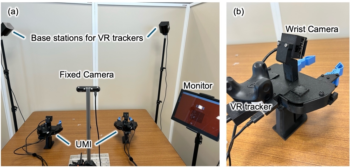
*図 1 (a) 姿勢推定に VR トラッカーを用いた UMI データ収集システム。(b) 人間のデモンストレーションに使用されたハンドヘルドデバイス。
課題
VR トラッカーは現実世界での軌道データ収集において堅牢な解決策を提供しましたが、学習済みポリシーを物理ロボットに展開する際には、全く異なるハードウェア課題が浮上しました。それは、関節の精密なキャリブレーションです。
UMI 研究では、ハンドヘルドデバイスを用いた人間のデモンストレーションを通じて収集されたデータに基づき、ロボットのエンドエフェクタが制御されます。ロボットアームが空間内の目標位置へ正確にエンドエフェクタを駆動させるためには、その関節のゼロ点調整(キャリブレーション)が極めて精密である必要があります。
これは一見すると当然の要件のように思えるかもしれません。しかし、標準的なテレオペレーションでデータを収集し、同じロボット上でポリシーを展開するシナリオでは、このゼロ点のズレはほとんど問題になりません。データ収集時と展開時の両方で、全く同じゼロ点のズレが生じているため、誤差はお互いに相殺されるからです。
UMI 関連の研究では UR シリーズや Franka Emika Panda のような高精度なロボットが一般的に使用されているため、この課題は明示的に議論されることはあまりありませんでした。
当チームは、Enactic が開発した「Openarm」*4 をベースに、QDD(Quasi-Direct Drive)モーターを搭載したカスタムロボットを開発しています。このような自作ロボットでは、通常、機械的なエンドストップを使用するか、基準姿勢を定義することでキャリブレーションを行います。しかし、組立公差や部品のわずかな差異により、実際の関節可動域と設計値の間に乖離が生じました。その結果、エンドエフェクタの位置に数センチメートルの誤差が発生しました。
このハードウェア上で UMI を成功裡に展開するためには、3 つの根本的な工学的課題に取り組む必要がありました。高度なアルゴリズムを適用するだけでなく、物理世界とのギャップを埋めるための地道な調整を実装することが求められたのです。具体的には、以下の 3 つの相互に関連する課題を解決する必要がありました。
- 計測:組立公差に起因する関節零点オフセット誤差の除去
- コントロール:高精度な手動キャリブレーション(ティーチング)に不可欠な重力補償による物理的コンプライアンスの実現
- コンピュータビジョン:広角フィールドオブビュー(FoV)を実現するためにレンズを交換した際に生じた内部パラメータのシフトの修正
以下のセクションでは、これら 3 つの重要な工学的アプローチについて詳しく解説します。
アプローチ:3 つの必須工学的支柱
1. 関節運動学キャリブレーション(計測)
ロボットアームがエンドエフェクタを正確に目標位置へ誘導するためには、各関節のゼロ点校正が不可欠です。この課題解決のため、私たちは産業用ロボティクスで広く採用されている「XYZ 4 点法」に基づく校正手法を実装することを選びました*5, *6。これは、ロボットが空間内の固定参照点(通常は鋭いピン先)へ、少なくとも異なる姿勢から 4 回以上アプローチする幾何学的な手法です。未知の TCP(ツールセンターポイント)が常にこの固定点と一致するようにすることで、ロボットの関節角度から TCP の位置ベクトルや関節オフセットを逆算して求めることができます。この幾何学的制約を基盤に、校正問題を最適化問題として定式化しました。
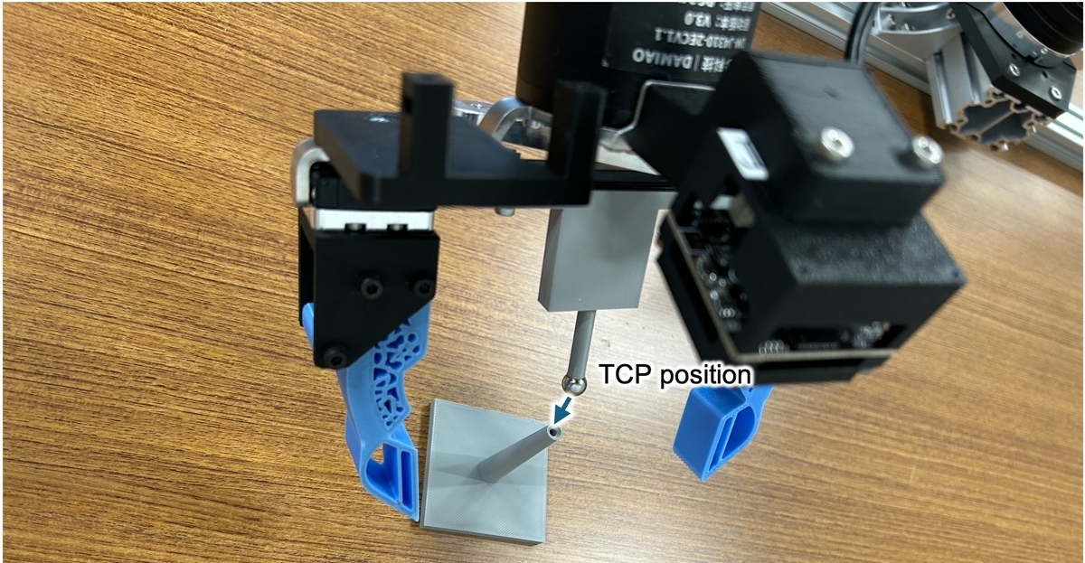
*図 2: TCP(ツールセンターポイント)の正確な位置を特定するために XYZ 4 点法で使用される、3D プリンタで製作可能な校正ツール。
この手法の中核となるのは、「異なる関節角度(姿勢)から、エンドエフェクタが空間内の全く同じ物理的点上に位置する」という幾何学的制約です。
ここで、
を取得した姿勢の数を、
を
番目の姿勢における測定された関節角度とし、
(7DoF アームの場合、
ただし、
と、
は、見つけたい「真のオフセット補正値」です。ロボットの順運動学を関数
と定義すると、各姿勢における計算された TCP 座標
は以下のように表せます。
現実世界では、ロボットは物理的に全く同じ点を触っています。したがって、
が完璧な値であれば、計算された
はすべての姿勢
において完全に一致するはずです。しかし、初期状態にオフセット誤差が含まれているため、この点群にはばらつきが生じます。これらの点の重心(平均座標)を
と定義します。
最適化の目的は、以下の値を見つけることです。
各TCP座標間の距離(分散)を最小化する
そして重心
具体的には、以下の目的関数を最小化する最適化問題として定式化します。
物理 AI の舞台裏:カスタム QDD ロボットアームのための UMI データ収集
物理 AI の発展には、ロボットが現実世界で動作するための膨大なデータが必要です。特に、複雑な制御や多様なタスクをこなすためには、高品質なデータセットの構築が不可欠です。この記事では、UMI(Universal Manipulation Interface)プロジェクトの一環として行われた、カスタム QDD ロボットアーム向けのデータ収集プロセスについて詳しく解説します。
QDD(Quasi-Direct Drive)ロボットアームは、従来の減速機を使用しない設計により、高い応答性と精密なトルク制御を実現しています。しかし、その特性を活かすためには、専用の学習データが求められます。UMI は、この課題に対応するために、特定の QDD ロボットアームを用いた大規模なデータ収集実験を行いました。
データ収集の手法は、人間の操作者によるテレオペレーションと、自動生成されたタスクを組み合わせたハイブリッドアプローチを採用しています。人間がジョイスティックやモーションキャプチャ装置を使用してロボットを制御し、その動作データを記録します。同時に、事前に定義されたタスクセットに基づいて、ロボットが自律的に動作する様子を収集しました。
収集されたデータには、視覚情報(カメラ映像)、触覚情報(力覚センサー)、そして関節の位置や速度などの状態情報が含まれています。これらの多様なモダリティを統合し、物理 AI モデルが現実世界を理解し、予測し、制御するための基盤としています。
UMI プロジェクトのデータ収集は、単なるデータの蓄積に留まりません。収集されたデータは、オープンソースとして公開され、研究コミュニティ全体で利用可能な形で提供されています。これにより、物理 AI の分野における研究開発が加速し、より汎用的なロボット制御技術の実現に向けた一歩となっています。
今後の展望として、UMI データセットを活用した新しいアルゴリズムの開発や、異なる種類のロボットアームへの適用拡大が期待されています。物理 AI が現実世界でどのように進化していくか、その最前線を支える重要な要素の一つが、このデータ収集プロジェクトなのです。
最初の項はエンドエフェクタの位置の分散を最小化する。2 番目の項は正則化ペナルティであり、
これは、エンコーダーと機械設計の値から導き出された「物理的に可能な最大の誤差」です。最適化アルゴリズム(ここでは微分進化法を使用)が非現実的なほど大きな補正値を出力しないよう、微小な重みを乗じることで制約を設けています。
タイトル(参考のみ・出力に含めない): Behind the Scenes of Physical AI: UMI Data Collection for a Custom QDD Robot Arm
物理AIの舞台裏:カスタムQDDロボットアームのためのUMIデータ収集
物理AIの実現には、ロボットの動作を学習させるための膨大なデータが必要です。特に、複雑な環境で柔軟に操作を行うためには、人間のような自然な動きや、多様な物体への対応が求められます。このため、研究チームは「UMI(Universal Manipulation Interface)」と呼ばれるデータ収集フレームワークを用いて、カスタム設計のQDD(Quasi-Direct Drive)ロボットアーム向けのデータを構築しました。
UMIは、単なるロボット制御ではなく、人間とロボットの相互作用を記録・分析するための包括的なプラットフォームです。ここでは、人間の操作者がジョイスティックやモーションキャプチャーデバイスを用いてロボットを遠隔操作し、その際のセンサーデータ(関節角度、トルク、カメラ映像など)がすべて記録されます。これにより、ロボットは「人間がどうやって物体をつかむか」「どうやって配置するか」という実用的な知識を獲得できます。
カスタムQDDロボットアームの特徴として、高い応答性と滑らかな動きが挙げられます。従来の減速機付きモーターとは異なり、QDDは直接駆動に近い構造を採用しており、より精密な制御と力覚フィードバックが可能です。UMIデータ収集では、このアームの特性を活かすため、高頻度でのサンプリングと低遅延の通信が重視されました。
データ収集プロセスは、以下のステップで進行します。
- 環境設定:多様な物体(形状、材質、重さの違い)を配置した実験台を用意。
- 操作者トレーニング:人間にロボット操作の基本的なスキルを習得させる。
- データ記録:ジョイスティックやモーションキャプチャーによる操作と、ロボットのセンサーデータを同期して保存。
- バリデーション:収集データの品質を確認し、ノイズ除去や補正を実施。
UMIで収集されたデータは、ロボットが未知の物体を認識し、適切な把持戦略を選択する能力を高めるために活用されます。また、強化学習や模倣学習のトレーニングデータとしても利用可能です。これにより、物理AIは単なる決定的な動作ではなく、状況に応じた柔軟な判断が可能になります。
今後の展望として、UMIフレームワークはさらに拡張され、より複雑なタスク(例:複数物体の同時操作、動的環境での対応)への対応が期待されています。また、他のロボットプラットフォームとの互換性も検討されており、物理AIの研究コミュニティ全体でのデータ共有が進むことが予想されます。
物理AIの実現には、データの質と量が不可欠です。UMIによるカスタムQDDロボットアーム向けのデータ収集は、その重要な一歩となっています。
さらに、XYZ 4 点法では人間がロボットを特定の点に手動で誘導・整列させる必要があるため、手の震えや視覚的な整列の限界によって、測定値にばらつきが生じるのは避けられません。今後の精度向上のためには、空間上の単一点への整列ではなく、エンドエフェクタを平面に押し付けて接触させる「平面接触法」*7 などの代替アプローチを採用する方が有益かもしれません。
2. 重力補償とコンプライアンス(制御)
ロボットは QDD モーターを採用しているため、極めて透明性の高いトルク制御を活用できます。しかし、このハードウェアの能力を真に引き出すには、正確な重力補償コントローラーの実装が不可欠です。
制御の観点からなぜこれが不可欠なのかを理解するために、フィードフォワード重力項を含む標準的な剛体ダイナミクスと PD(比例微分)制御則を見てみましょう*8。
ここでは、
は慣性行列である。
はコリオリ項・遠心項である。
重力である。
ロボットに印加される外部トルク(例:人間が押す力)のことです。制御則では、
物理 AI の舞台裏:カスタム QDD ロボットアームのための UMI データ収集
ロボット工学におけるデータ収集の重要性は、特に学習ベースのアプローチにおいて極めて高い。従来のシミュレーション環境では、現実世界との乖離(sim-to-real gap)が常に課題となってきた。そこで注目されているのが、UMI(Universal Manipulation Interface)というフレームワークだ。
UMI は、汎用的なロボット操作タスクを効率的に収集・構築するためのデータプラットフォームとして設計されている。このシステムは、多様なロボットアームやエンドエフェクタに対応し、人間による実機操作を通じて高品質なデータを自動記録する仕組みを持つ。
本稿では、UMI を用いてカスタム QDD(Quasi-Direct Drive)ロボットの動作データを収集した事例を紹介する。QDD ロボットは、高いトルク密度と滑らかな制御特性を備えた次世代アクチュエータを採用しており、従来のモーター駆動型ロボットとは異なる挙動を示す。そのため、既存のデータセットではカバーしきれない独自の動作パターンを学習させる必要がある。
UMI を活用することで、研究者は複雑な物理環境下でのロボット操作データを迅速に収集できる。人間オペレーターが実際にアームを動かしながら、視覚情報や力覚フィードバック、関節角度などの多様なセンサーデータを同期して記録する。このプロセスにより、シミュレーションでは再現困難な現実世界のノイズや不確実性もデータセットに組み込むことが可能になる。
収集されたデータは、ロボットが物理世界でタスクを遂行するための基盤となる。例えば、物体の把持、移動、積み上げといった基本的な操作から、複雑な環境下での適応的動作まで、多様なシナリオに対応した学習が可能だ。UMI のようなシステムが普及することで、物理 AI の開発スピードはさらに加速すると期待されている。
今後の展望として、UMI によるデータ収集の自動化や、他社製ロボットとの互換性向上も進められている。これにより、より広範な研究コミュニティが物理 AI の発展に貢献できるようになるだろう。
は、目標関節角度と現在の関節角度である。
制御ゲインです。
指令トルク(
を代入すると、
ダイナミクス方程式に代入すると、重力項は
完全に相殺されます。アームを手でゆっくり動かす準静的状態を仮定すれば、速度は
加速度
この式は以下のように簡略化されます:
もし正確に計算して注入しなかった場合、
この場合、PD コントローラーだけでは重力と戦わなければなりません。アームがたわむこと(定常誤差)を防ぐためには、比例ゲインを高く設定せざるを得なくなります。
極めて高い水準である。高品質な
ロボットアームが本質的に硬く、剛性が高くなる原因となります。
重力を明示的にキャンセルすることで、PD コントローラは軌道追跡誤差のみを処理すればよくなります。これにより、大幅に低い制御ゲインを使用することが可能になります。
物理 AI の舞台裏:カスタム QDD ロボットアームのための UMI データ収集
ロボット工学におけるデータ収集の重要性は、学習モデルの性能を決定づける鍵となります。特に、汎用的な物理操作を実現する「Physical AI」の開発においては、高品質で多様な実世界データの確保が不可欠です。
本稿では、UMI(Universal Manipulation Interface)プロジェクトの一環として行われた、カスタム QDD ロボットアーム向けのデータ収集プロセスについて詳述します。QDD(Quasi-Direct Drive)は、高いトルク密度と精密な制御を両立させる駆動方式であり、複雑な作業タスクに適したロボットアームの実現に寄与しています。
UMI データセットの構築では、単なる動作の記録にとどまらず、多様な環境下での物理的相互作用や、人間との協調作業におけるニュアンスまでを捉えることを目指しました。収集されたデータは、ロボットの知能化に向けた基盤として活用され、より柔軟で信頼性の高い操作システムの開発に貢献しています。
この取り組みを通じて、私たちはロボットが未知の環境に適応し、複雑なタスクを遂行する能力を飛躍的に高める可能性を探っています。
この低ゲイン制御と、QDD モーターが本来持つ低い機械摩擦が組み合わさることで、アームは真の物理的コンプライアンス(柔軟性)を獲得します。
このコンプライアンスは手動操作において極めて有益です。例えば、前述の XYZ 4 点キャリブレーションでは、現在の関節角度に合わせて目標となる関節角を継続的に更新しています(
これにより、アルゴリズムによる復元力がゼロになります(
これにより、モーターと戦うことなく、TCP を手動でシームレスかつ精密に誘導することが可能になります。
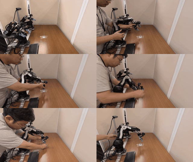
図 3:重力補償制御下で行われる手動キャリブレーションのプロセス。
3. カメラ内部パラメータのキャリブレーション(コンピュータビジョン)
最後に、視覚ドメインを一致させるためにカメラハードウェアの対応も必要でした。今回のセットアップでは、より広い視野角を実現するために標準的な USB カメラレンズを交換しました。一見単純なハードウェア改造のように思えますが、レンズとマウントを取り替えるだけで、画像中心(主点)が大きくずれるだけでなく、新たなレンズ歪みが生じるのが一般的です。
図 4(b) に示す通り、レンズマウントはネジで固定されているため、組み立て時にわずかなズレが発生しやすく、個々のカメラユニット間で差異が生じることがあります。コンピュータビジョンにおいて、OpenCV ライブラリを活用した厳密な内部パラメータ(イントリック)キャリブレーションは、基本的かつ不可欠な手順です。これを省略すると、カメラの視覚観測と物理的な動作空間との空間マッピングがずれてしまい、人間によるデモデータとロボットの実際の動作実行に重大な乖離が生じます。
さらに、ハンドヘルドデバイスの TCP と VR トラッカー間の相対姿勢を推定し、全体の空間整合性を確保するために 4 点法も併用しました。
原文を表示
Hello, I'm Hideyuki Ichiwara from the Robotics Team. Our team is currently developing Vision-Language-Action (VLA) models with the goal of realizing general-purpose foundation models for robots. In this article, I would like to introduce the data collection approach we are actively working on.
What is UMI?
Universal Manipulation Interface (UMI)*1 is a low-cost, universal data collection device and learning framework proposed by Stanford University and the Toyota Research Institute (TRI). By using a handheld device equipped with a camera that mimics a robot's gripper, humans can collect data simply by demonstrating tasks across various environments. This approach leverages a robot-agnostic representation based on the end-effector pose, enabling the acquisition of generalized policies independent of the specific robot model, provided the gripper and camera conditions are consistent.
In the original research, the trajectory of the end-effector's pose was estimated based on images from an action camera and IMU data. However, the estimation performance heavily depended on background conditions (such as the richness of visual features) and how the hand was moved, which led to challenges in data efficiency. To address this, our team is exploring an approach that measures the end-effector pose using alternative tracking methods such as VR trackers (Fig. 1), established in several prior works*2, *3. However, the key point of this report is not just the use of VR trackers. While building this high-precision data collection system, we discovered a significant gap between the hardware and the system when deploying the learned policy onto our physical custom robot. Therefore, the core focus of this article is to introduce three unglamorous yet essential engineering efforts across Measurement, Control, and Computer Vision that were required to successfully make this VR tracker-based UMI system work on a real-world custom robot.
Challenges
While VR trackers provided a robust solution for collecting trajectory data in the real world, deploying that learned policy onto a physical robot introduced a completely different hardware challenge: precise joint calibration. In UMI research, the robot's end-effector is controlled based on data collected via human demonstrations using a handheld device. For the robot arm to accurately drive its end-effector to the target position in space, its joints must be precisely calibrated (zero-point adjustment).
This might sound like an obvious requirement. However, in scenarios where data is collected via standard teleoperation and the policy is deployed on the exact same robot, this zero-point deviation is rarely an issue. Since the exact same zero-point deviation is present during both data collection and deployment, the errors effectively cancel each other out. In many UMI-related studies, high-precision robots like the UR series or Franka Emika Panda are typically used, so this issue was rarely discussed explicitly.
Our team is developing with a customized robot based on the "Openarm"*4 developed by Enactic, which is driven by QDD (Quasi-Direct Drive) motors. For such custom-built robots, calibration is typically performed using mechanical end stops or by defining a reference posture. However, due to assembly tolerances and minor part discrepancies, a gap emerged between the actual joint ranges and their design values. This resulted in an end-effector positioning error of several centimeters.
To successfully deploy UMI on this hardware, we had to address three fundamental engineering pillars. Rather than just applying advanced algorithms, we needed to implement gritty adjustments to bridge the gap with the physical world. Specifically, we had to resolve the following three interconnected challenges:
- Measurement: Eliminating the joint zero-point offset errors caused by assembly tolerances.
- Control: Achieving physical compliance through gravity compensation, which is necessary for high-precision manual calibration (teaching).
- Computer Vision: Correcting the shift in intrinsic camera parameters that occurred when we changed the lens to achieve a wider Field of View (FoV).
In the following sections, we will detail these three essential engineering approaches.
Approach: 3 Essential Engineering Pillars
1. Joint Kinematics Calibration (Measurement)
For the robot arm to accurately drive its end-effector to the target position, its joints must be precisely zero-point calibrated. To resolve this, we decided to implement a calibration method based on the XYZ 4-point method*5, *6, a technique widely used in industrial robotics. This is a geometric method where the robot approaches a fixed reference point in space (usually a sharp pin tip) from at least four different postures. By ensuring the unknown TCP (Tool Center Point) consistently matches this fixed point, we can back-calculate the TCP position vector and joint offsets from the robot's joint angles. Building upon this geometric constraint, we formulated the calibration as an optimization problem.
The core of this method relies on a geometric constraint: "The end-effector is aligned with the exact same physical point in space from different joint angles (postures)."
Let
be the number of acquired postures,
be the measured joint angles at the
-th posture (for a 7-DoF arm,
), and
be the "true offset correction value" we want to find. If we define the robot's forward kinematics as a function
, the calculated TCP coordinate
at each posture can be expressed as:
In the real world, the robot is touching the exact same physical point. Therefore, if
is perfect, the calculated
should perfectly coincide across all postures
. However, because the initial state contains offset errors, there will be variance in this set of points. We define the centroid (average coordinate)
of these points as:
The goal of the optimization is to find a
that minimizes the distance (variance) between each TCP coordinate
and the centroid
. Specifically, we formulate this as an optimization problem minimizing the following objective function
:
The first term minimizes the variance of the end-effector positions. The second term is a regularization penalty, where
is the "maximum physically possible error" derived from the encoder and mechanical design values. To prevent the optimization algorithm (we used Differential Evolution) from outputting unrealistically large correction values, we apply a constraint by multiplying a tiny weight
(e.g.,
).
Furthermore, because the XYZ 4-point method requires a human operator to manually guide and align the robot to a specific point, slight hand tremors or limitations in visual alignment inherently introduce some measurement variance. To further improve accuracy in future work, it might be beneficial to adopt alternative approaches, such as the plane-contact method*7, which relies on pressing the end-effector against a flat surface rather than aligning it to a single point in space.
2. Gravity Compensation and Compliance (Control)
Because our robot utilizes QDD motors, we can take advantage of highly transparent torque control. However, to truly unlock this hardware capability, implementing an accurate gravity compensation controller is absolutely vital.
To understand why this is essential from a control perspective, let's look at the standard rigid-body dynamics combined with a PD (Proportional-Derivative) control law that includes a feedforward gravity term*8:
Here,
is the inertia matrix,
is the Coriolis/centrifugal term, and
is gravity.
is the external torque applied to the robot (e.g., human pushing). In the control law,
and
are the desired and current joint angles, and
are the control gains.
By substituting the commanded torque (
) into the dynamics equation, the gravity term
perfectly cancels out. If we assume a quasi-static state where the arm is moved slowly by hand (velocity
, acceleration
), the equation simplifies to:
If we did not accurately compute and inject the
term, the PD controller alone would have to fight gravity. To prevent the arm from sagging (steady-state error), we would be forced to set the proportional gain
extremely high. A high
makes the robotic arm inherently stiff and rigid.
By explicitly canceling gravity, the PD controller only needs to handle trajectory tracking errors. This allows us to use significantly lower control gains (
and
). It is this low-gain control, combined with the inherently low mechanical friction of QDD motors, that grants the arm true physical compliance.
This compliance is extremely beneficial for manual operations. For example, during the XYZ 4-point calibration mentioned earlier, we continuously update the target joint angles to match the current ones (
). This zeroes out the algorithmic restoring force (
), allowing us to seamlessly and precisely guide the TCP by hand without fighting the motors.
3. Camera Intrinsic Calibration (Computer Vision)
Finally, to match the visual domain, we had to address the camera hardware. In our setup, we replaced the standard USB camera lens to achieve a wider field of view. While this sounds like a simple hardware modification, changing a lens and lens mount almost always causes the image center (principal point) to shift significantly, alongside introducing new lens distortion. As shown in Fig. 4 (b), the lens mount is secured with screws, meaning that slight misalignments can easily occur during assembly, leading to individual discrepancies between each camera unit. Performing a rigorous intrinsic camera calibration—for which we utilized the OpenCV library—is a basic but essential procedure in computer vision. Skipping it means the spatial mapping between the camera's visual observations and the physical action space will be misaligned, leading to a critical discrepancy between the human-demonstrated data and the robot's execution. We also used the 4-point method to estimate the relative pose between the handheld device's TCP and the VR tracker to ensure total spatial consistency.
関連記事
今日のまとめ
AIデイリーブリーフで今日の重要ニュースをまとめ読み